-40%
12 Multifunctional Car Diagnostic Tester Set Digital Oscilloscope Multimeter USA
$ 63.35
- Description
- Size Guide
Description
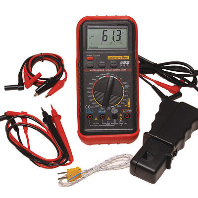
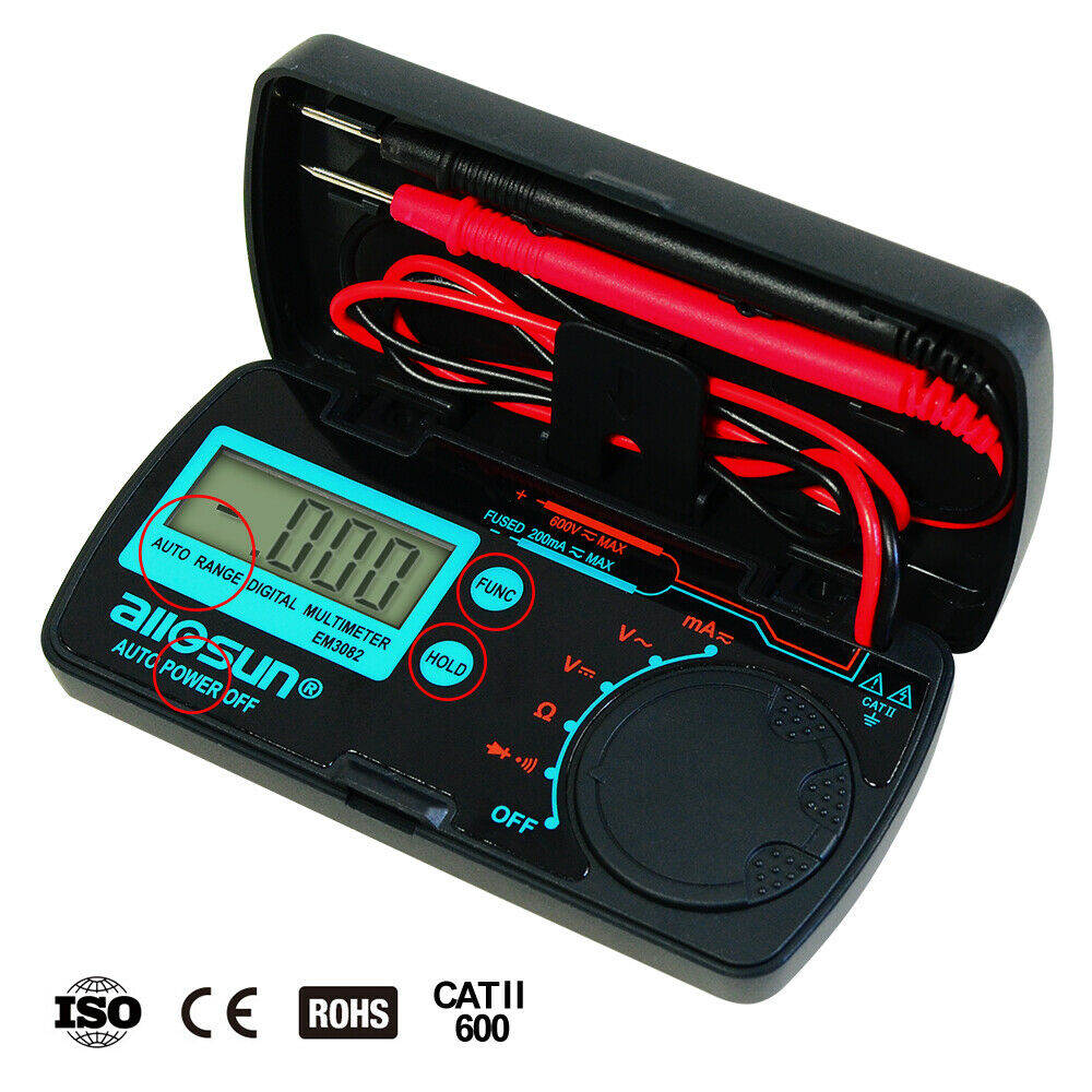
【Multifunction Digital Multimeter Function】 New handheld diagnostic oscilloscope multimeter designed with embedded digital control technology, integrating digital oscilloscope, digital multimeter, automotive circuit, automotive signal check and other functions in one. The multimeter mode can measure the AC / DC voltage and current, resistance, diode forward voltage drop, on-off and frequency.【Excellent Oscilloscope Performance】Oscilloscope mode is a complete intelligent measurement system, which includes signal input, data sampling, data processing and automatic search, with the waveform test bandwidth of500KHZ. With a variable sampling frequency, the slowly varying signal amount can be measured.
【Car diagnostic universal Multimeter】 Car circuit detection can online test the low voltage circuit, prompt high voltage or line leakage and output the power supply voltage. It can also output the power voltage to test the parts of the car, or lower the voltage to drive the parts of the car, such as lights; Test the battery voltage when the oil-fueled vehicle starts, and judge whether the vehicle starting system and the battery are in good condition.
【Great Power Management】Input impedance for the voltage measurement: it is 2~3MΩ when the voltage is lower than 160V; it is 10MΩ when the voltage is higher than 160V. The maximum input voltage is 1000Vpp; The analog bandwidth is 500KHz; The voltage range is converted automatically; the 10A terminal fuse for current measurement is 15A self-recovery fuse, and the maximum measurable current is 20A; The current measurement mA/uA terminal fuse is 0.5A self-recovery fuse.
【Automotive circuit/start-up / fuel injector/relay test】The analog signal output can be applied to the car ECU detection and can simulate the square wave and sine wave output and simulate the fuel injection signal to drive the fuel injection nozzle; Check the data signal K line and CAN bus signal in the vehicle.
【Widely Used】It is applicable to measuring and observing various signals on the automobile circuit during the car overhaul, including the motor drive signal and motor power voltage of new energy vehicle, fuel car engine ignition pulse signal, camshaft signal, crankshaft signal, wheel speed sensor signal, oxygen sensor signal and so on.
【3 year Warranty 】If you have any questions, please feel free to contact us, we are sure to provide you a satisfied solution within 24 hours. For damage caused by non-human factors, we promise to resend parts for free within three years.
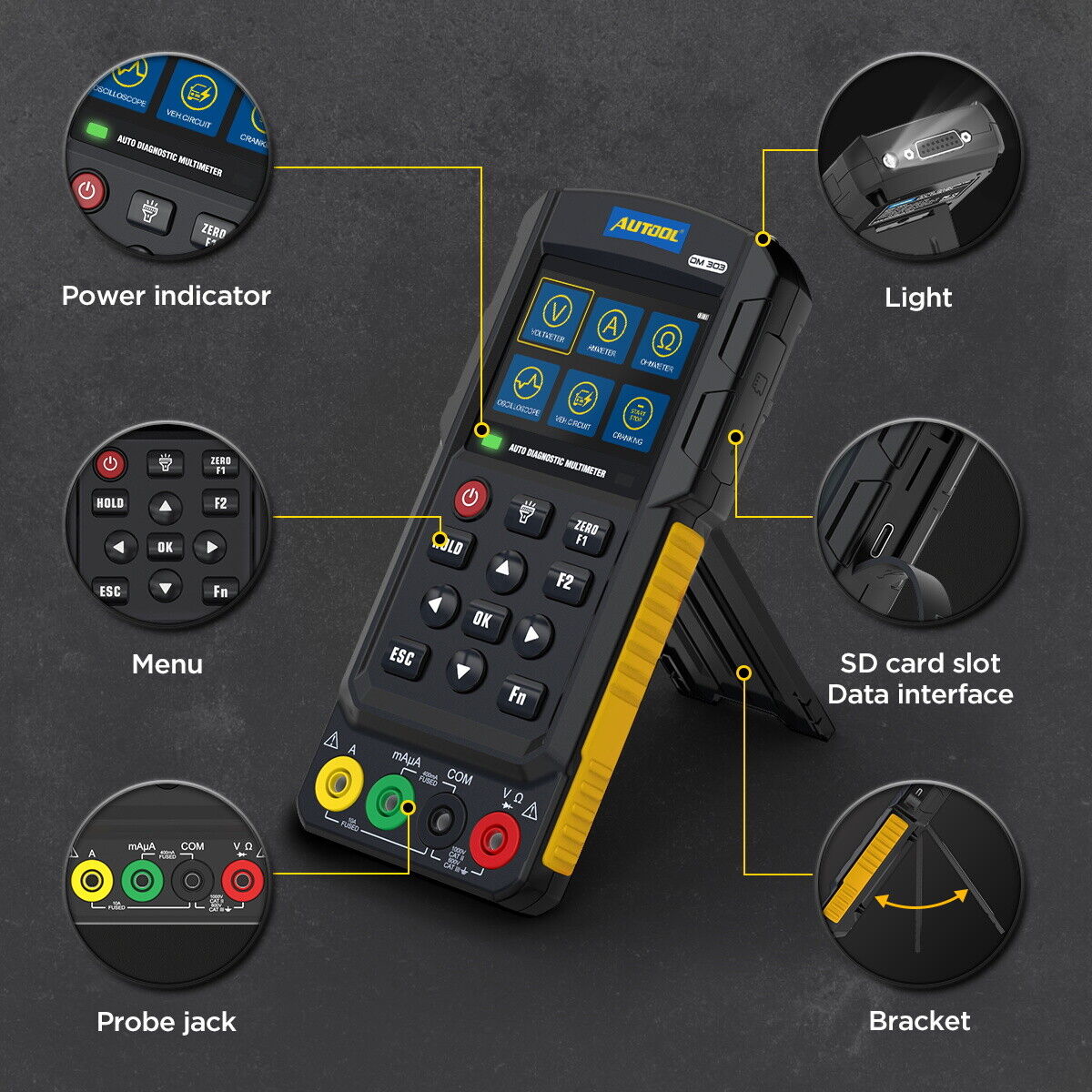
The multimeter function and the oscilloscope function areintegrated together on the instrument. When measuring thevoltage signal using a probe, switch to the oscilloscope function with [Fn] key to facilitate the use and observation of signal waveform.
Safe operation guidelines
· Before use, check that the insulation layer of the probe is intact without damage or breakage. If any obvious damage to insulation of probe or instrument shell, or you believe that the instrument cannot work normally, please do not use the instrument any more.
· While using a probe, put your fingers behind its finger protection ring. Before using the instrument, remove the USB charging cable. Do not apply voltage above 1000Vrms between instrument terminal and grounding terminal to prevent electric shock and instrument damage. In case of measured voltage higher than DC60V and 42Vrms, be careful to prevent electric shock.
· Before covering up the rear cover of the instrument, it is strictly forbidden to use the instrument; otherwise there will be risks of electric shock.
· Measured signals are not allowed to exceed the regulated limit value to prevent electric shock and instrument damage.
· It is not allowed to use current to test terminals or voltage at current gear.
· A self-recovery fuse is used inside the instrument. Do not change the internal wiring of the instrument to avoid damaging the instrument and endangering safety.
· When the battery symbol is shown in red on the LCD, the battery should be charged or replaced timely to ensure the measurement accuracy.
· Do not operate the instrument in the high temperature, high humidity environment. Especially, do not store the instrument in the wet environment, as the instrument performance may deteriorate if being wetted.
· Clean the instrument enclosure with a wet cloth and a gentle detergent, and do not use abrasive agents or solvents.
Parameter
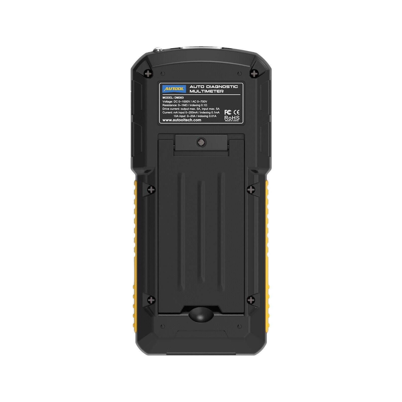
LCD is a 2.8-inch color screen, with a resolution of 320*240;
Input impedance for the voltage measurement: it is 2~3MΩ
when the voltage is lower than 160V; it is 10MΩ when the
voltage is higher than 160V. The maximum input voltage is
1000Vpp; The analog bandwidth is 500KHz; The voltage
range is converted automatically;
The 10A terminal fuse for current measurement is 15A self-recovery fuse, and the maximum measurable current is 20A; The
current measurement mA/uA terminal fuse is 0.5A self-recovery fuse, and the maximum measurable current is 200mA;
Working temperature: 0~40°C(32~104°F) Humidity: ≤75%;
Storage temperature: 10~50°C(14~122°F) Humidity: ≤70%;
Altitude: 2000m.
OPERATIONS INSTRUCTION
-The instrument is equipped with a power switch and the automatic sleep function. The automatic sleep time can be set to 1-30 minutes. The key tone of the instrument can be set to turn on and off, but the warning tone cannot be turned off. The
brightness of the screen can be set. The brightness can be set according to the actual operation environment, and the battery time can be extended by appropriately lowering the brightness.
-The help function of the instrument provides a brief operation
description.
-The instrument is configured in one or more languages
according to the sales area. Please contact your local dealer
for different languages.
-After turning on the power supply, according to the displayed
icon, use the [up/down/ left /right] direction keys to move the
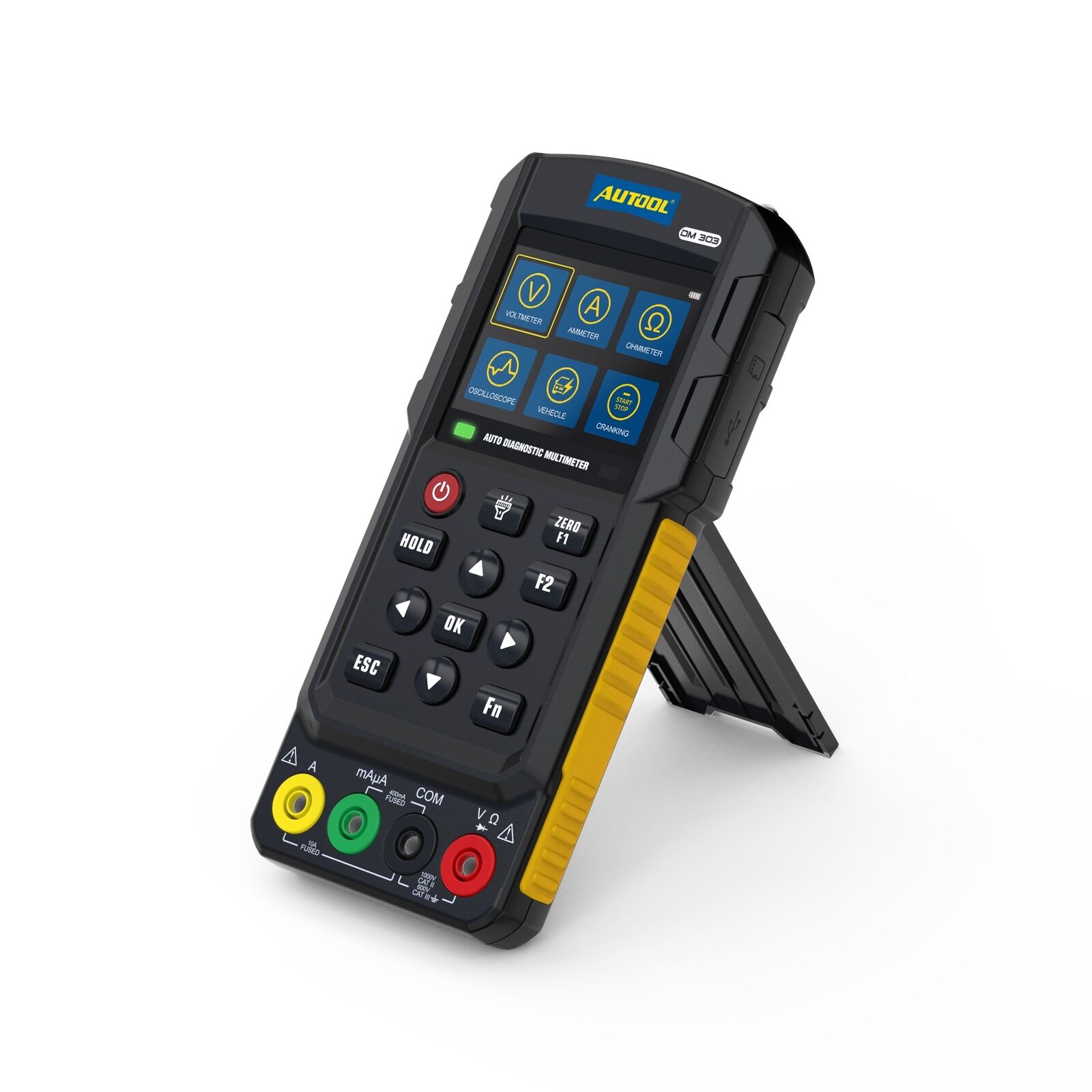
current option, and press [OK] to enter the function item.
Package include
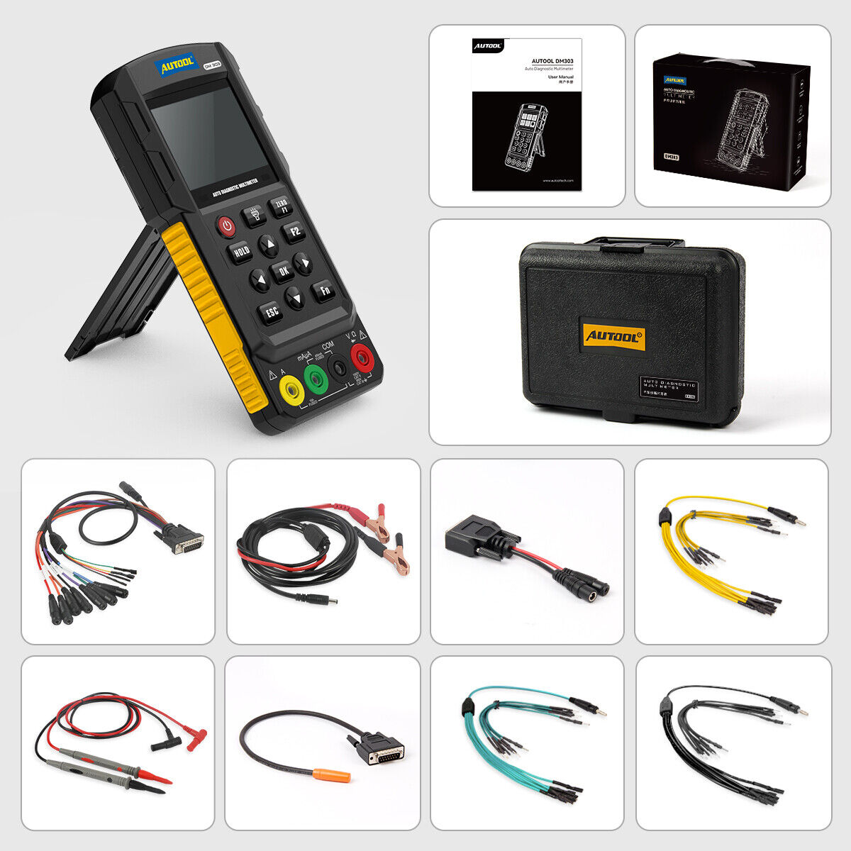
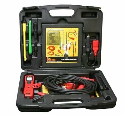
1 x DM303 Multimeter
1 x Multifunctional functional detection line
1 x Automotive circuit detection line
1 x Ignition signal detection line
1 x Battery clip line
1 x Jumper(Yellow)
1 x Jumper(Green)
1 x Jumper(Black)
1 x Probe
1 x Suitcase
1 x Instruction manual
Voltage measurement
The current measured value is displayed. If the voltage fluctuates, press the [HOLD] key to maintain the display status. If there is no voltage signal, the displayed value is non-zero, the red and black probe can be shorted, and press the [F1] key at the same time to perform the quick zeroing operation. [F2] key is used to remove the induction power at the measurement point. Press [F2] key during the measurement, which is equivalent to a 10K resistance connected the red and black probe. This function is suitable for detecting the induction voltage of
the new energy vehicle. Press [Fn] key to switch to the AC voltage measurement and the oscilloscope mode to observe
the signal waveform; In the voltage measurement or oscilloscope mode, the range is automatically converted, and the
maximum measurable voltage signal is 1000V; In the voltage measurement mode, the probe only inputs signal, but no pulse signal, without interference to the measured point.
Oscilloscope
Display the current signal waveform, 5V/grid - display the voltage scale value, and press the [up] and [down] keys to change during measurement; 1ms-scan time scale value;
during measurement, press the [left] and [right] keys to change; Trigger+01 - displays the correction value of the trigger level, which can be changed by pressing [F1 / F2]. The trigger level is the average value of the current waveform automatically calculated. The positive value of trigger correction indicates the increase value of trigger level correction, and the negative value of trigger correction indicates the decrease
value of trigger level correction;
Press the [HOLD] button to pause the display of the waveform.
When the waveform is suspended, the [up / down / left /right]keys can be used for the left and right movement control of the
waveform, so as to facilitate the comparison and observation of the waveform.
Current measurement
The current measured value is displayed. If the current fluctuates, press the [HOLD] key to maintain the display status. If
there is no current signal, the displayed value is non-zero, the red and black probe can be shorted, and press the [F1] key at
the same time to perform the quick zeroing operation. [F2] key is used to switch the large current measurement, [Fn] key is
used to convert measurements of DC current and AC current.
Resistance test
The instrument detection resistance and the diode are two-in-one function display. Press [Fn] key to switch the display mode. When measuring the resistance, the resistance
can be set as the main display; when measuring the diode, the diode can be set as the main display; As shown in the following
figure:
The resistance value displayed is the resistance value when measuring the resistance, and the voltage value displayed is
the pressure drop value when measuring the diode. Connect the red and black probe, and press [F1] key for zeroing. If the
resistance is excessive low, the instrument will give a sound prompt.
Automotive circuit test
Insert the special wire for automobile circuit into the multi-functional interface (top of the machine), connect the battery clip
line, clamp the red clip on the positive plate of the automobile battery, clamp the black clip on the negative plate of the automobile battery, and use the probe to detect the automobile circuit. During the detection process, the probe will send a test
signal to detect the electric leakage of the circuit.
Car start-up test
Insert the multi-function detection line into the multi-function interface (the top of the machine), connect the battery clip line,
clamp the red clip on the positive plate of the car battery, clamp the black clip on the negative plate of the car battery, and turn
off the car engine;
Injector test
The instrument can directly drive the injector for testing, and can also detect the real-time injector signal of the vehicle; Insert the multi-function detection line into the multi-function interface (top of the machine), connect the battery clip line, clamp the red clip on the positive plate, clamp the black clip on
the negative plate, and connect the removed injector to the
multi-function line, as shown in the figure below:
Automobile relay test
Insert the multi-functional detection line into the multi-functional interface (top of the machine), connect the battery clip line, clamp the red clip on the battery positive plate and the black clip on the battery negative plate. The red clip of the C01-2 transfer line is clamped at the bottom of a coil of the relay, the black clip is clamped on the bottom of the other coil of the relay, insert the red probe into the Ω jack, and the black probe into the COM jack
Analog signal test
The instrument analog outputs basic square wave and sine
wave signals. If other signal simulation is required, contact the manufacturer to customize non-standard products.
The independent output signal of the instrument is a square
wave close to 5V and a sine wave close to 5Vpp. If 12V square wave needs to be generated, the battery needs to be connected for power supply. Insert the multi-function detection line into the multi-function interface (the top of the machine). If the 12V square wave signal is required, then connect the battery clip line and connect to the battery;
Ignition pulse signal test
Insert the Ignition pulse signal detection line into the multifunctional interface (top of the machine).
Close to the sensor head (top yellow area) to the ignition of the
engine cylinder.


